Here’s how I set up model matching for use with VATSIM tower view in MSFS2020. Honestly, it’s the same model matching I use for flying on VATSIM too. It works well.
FSLTL is great for people flying airliners for real airlines. It is not designed for GA aircraft or people flying MSFS default aircraft under non-airline callsigns.
To fix that download the custom rule sets by Marcus Griep. This includes rules for standard, deluxe, and premium MSFS aircraft, as well as common GA aircraft from Carenado, India Foxtrot Echo, and Kitfox. I don’t bother using the rules for Cape Air or the Mega Pack.
Step 3: Get my GA matching supplement rules
I used Model Matching Magic to make an additional rule file that covers some other GA aircraft and tries to at least get *something* to match for certain aircraft types. Download my custom rule set and put it somewhere safe.
Step 4: Add the rules to vpilot
Order matters. The list should be:
FSLTL_Rules.vmr
Carenado_C182.vmr
Carenado_C182_Similar.vmr
Carenado_M20R.vmr
Carenado_M20R_Similar.vmr
IFE_LongEZ.vmr
Kitfox_STi.vmr
MSFS_Premium.vmr
MSFS_Premium_Similar.vmr
MSFS_Deluxe.vmr
MSFS_Deluxe_Similar.vmr
MSFS_Standard.vmr
MSFS_Standard_Similar.vmr
GA_Matching_Supplement.vmr
Step 5: Enjoy!
That’s it. Now you have great model matching for tower view or flying on VATSIM.
It’s got better and easier to understand documentation
It’s easier to get firmware installed when your board arrives
It’s impossible to brick, you can always put it in bootloader mode
The only little gotcha is the RP2040 runs at 3V3 instead of 5V, which means you may need to use a level shifter with certain ICs (most notably the MAX7219) for safe operation.
Got an Arduino Nano or Arduino Mega? Did it work fine for years and now doesn’t work with Windows 11? Did you just get new ones from Amazon and tried to connect it to Windows 11 only to find it doesn’t work?
It’s not you. It’s the CH340 chip and a new Windows 11 driver not playing well together.
How do I know I have an affected Nano?
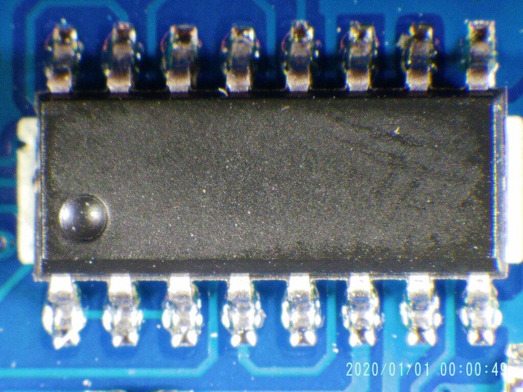
Look on the back of the Nano for the big rectangular chip. Is it blank, like in this photo? If the answer is yes then you have a Nano made with what is likely a counterfeit CH340 chip and it is affected by this problem.
A counterfeit CH340 chip, identified by the lack of letters on the package.
For comparison here is what a presumably genuine CH340 chip looks like on a Nano that does not have connection issues:
EXIF_HDL_ID_1
What driver version causes the problem?
Driver version 3.8.2023.2, released 02/11/2023, is when the problem started. With this driver installed these Nanos cannot be connected to via the COM port.
Is there a driver version that works?
Yes. Version 3.5.2019.1, released 01/30/2019, works fine. It’s available several places online. One good source is SimHub’s copy.
Be aware that Windows Update will aggressively attempt to install the newer version of the driver. SimHub has released a tool that will automatically install the correct driver version and then tell Windows Update not to update it going forward.
What else can I do?
Only buy Nanos that have CH340 chips with writing on them. If you order from Amazon and get boards without the lettering return them as defective, get your money back, and order another brand that has proper CH340 chips on them. Check the one star reviews for people complaining in 2023 about the boards not working. Nanos from DORHEA are known bad and do not work, for example, and the recent reviews reflect that.
In January 2023 Microsoft/Asobo released “AAU1”, a massive overhaul of several default planes in Microsoft Flight Simulator 2020, including a complete rewrite of the CJ4.
People still seem to be confused by this update and often come to the Working Title Discord with questions. Here are answers to the common ones.
Do I still need to install the mod from the Working Title website?
No.
The plane was re-written from the ground up and all future updates ship directly with MSFS2020.
There is no need to install a mod anymore to get the latest and greatest.You should uninstall any Working Title CJ4 mod you may have in your community folder.
How do I install and find the Working Title CJ4 in flight sim then?
It is the default CJ4 in Microsoft Flight Simulator 2020 now. If you run MSFS2020 you have it, the “AAU1” update is downloaded automatically.
Simply search for “CJ4” in the plane list. The one that shows up is the one you want.
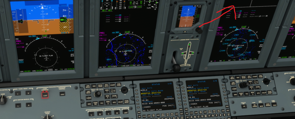
How do I know I have the re-written, latest and greatest, version?
Turn on the avionics. Look at the co-pilot’s MFD and verify it has a dedicated section for CAS messages at the top of the display (the two white rectangles):
They “rewrote” it so… is it better? What’s new with the plane?
The Cessna Citation CJ4 avionics have been heavily upgraded to bring an authentic CJ4 avionics experience:
Comprehensive visual overhaul for accurate font, symbology, look, operation, and feel
Independent MFD and FMS operation
Advanced flight plan support, including arcs, radius-to-fix, intercepts, hold, procedure turns, missed approaches, and custom waypoint scratchpad entry
Coupled VNAV with editable constraints, flight path angles, vertical path smoothing, and VNAV-invalidation conditions
Advanced autopilot, including armable lateral and vertical modes as well as complex combined-armed modes – Full specification-accurate TCAS II traffic system
Cabin pressurization and complete Crew Alerting System
FMS performance calculations for takeoff and landing speeds
Integrated dual engine FADEC systems with N1 mode indications and accurate N1 targets
Independent display options and state-saving
Enhanced FMS Text MFD display modes
Keyboard entry mode for FMS data entry
AHRS alignment and startup sequence
Improved flight model:
Improvements to ground and crosswind handing during the takeoff and landing phases
Improvements to flight control performance accuracy, smoothness, and handling
Improvements to fuel consumption accuracy
Improvements to handling while in ground effect
Improved engine and interior sound effects
What happened to Simbrief data import?
It was removed, but as of Sim Update 13 (released September 28, 2023) it is back. You can find it under IDX > ROUTE MENU on the FMC. See the Navigraph blog post for full details on how to set it up.
What happened to Navigraph Charts integration?
It’s gone. Navigraph has previously stated they don’t want to deal with forking the code to add chart support, which is understandable. As of SU15 there’s a plug-in model for the CJ4 that could make this easier, but apparently there are still a few missing pieces. WorkingTitle did make the necessary changes and they just need to make it into an MSFS2020 update.
What happened to ground power?
It was removed, but as of Sim Update 13 (released September 28, 2023) it is back. You can find it under IDX > USR SETTINGS. You still need to be parked at a gate that supports ground power for it to work.
The focus for the rewrite of the CJ4 was on avionics and flight model. The checklist feature was, unfortunately, cut due to time. The Working Title team has said it will be coming back though and they even posted a preview of it to the Discord! There is no announced release date for it, and it was not included in Sim Update 13.
What happened to the passenger briefing sounds?
They weren’t included in the rewrite due to rights reasons. Other sounds, like the 500′ callout, are supported because they reuse default sounds included in MSFS 2020.
My liveries don’t work anymore. What’s going on?
Most liveries have updated at this point to work with the rewritten CJ4. If you find one that isn’t working it is likely because it completely overrides the panel.cfg file, which is a no no. You can resolve the issue by replacing the livery’s panel.cfg file with the one from Working Title.
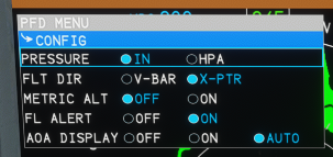
How do I change the barometric pressure units to metric (hectopascals)?
The CJ4 follows the real-world aircraft for changing pressure units. There are two separate systems, the PFD and the FMC.
For the PFD: Use the PFD MENU button to open the PFD options, then use the MENU ADV knob to scroll down to CONFIG. Press the MENU ADV knob to select it, then change the PRESSURE to either IN or HPA.
For the FMC: In the real world plane the pilot cannot change the unit used by the FMC. To work around this the CJ4 in the sim follows the unit set in the MSFS2020 options. Go to General Options > Misc and change Units of measurement to U.S. system or Metric system. You can also enter the pressure with a unit identifier after it, e.g. 1013H or 2992I, and the FMC will automatically swap to the appropriate unit.
Why does the plane refuse to take off until well after the Vr speed?
Nobody knows. This doesn’t happen for everyone, and it doesn’t happen all the time. There is no known workaround, all you can do is keep holding back on the yoke until the plane decides to take off.
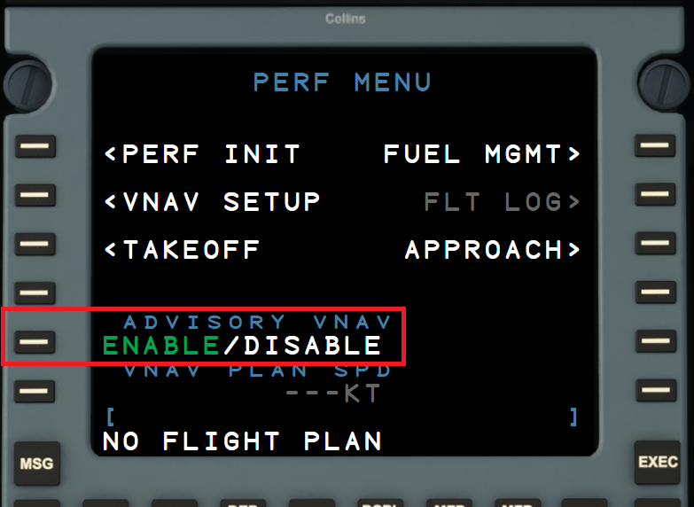
Why isn’t TOD/VNAV working?
VNAV works fine but does require some extra steps to get configured the first time. See my blog post on configuring VNAV for how to get it up and running.
I’m getting white screens. What’s going on?
You can resolve white screens by checking the following:
Make sure that you are not using old WT CJ4 mods of the plane or avionics packages
Make sure you don’t use an old livery that fully overrides panel.cfg (which only old obscure ones would still do)
If you are using the CJ4 Cockpit Texture mod then update it to the latest version
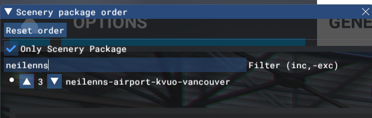
You only have to do this once. The plane will remember this setting for future flights.
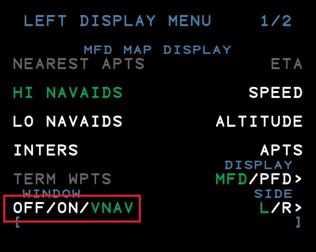
Step 2: Enable VNAV display on the MFD
Press the DSPL MENU button on the pilot’s FMC
Press LSK 6L until the WINDOW setting is VNAV
You only have to do this once. The plane will remember this setting for future flights.
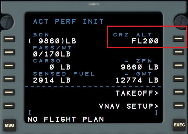
Step 3: Set your cruise altitude
Press the PERF button on the FMC
Press LSK 1L to select PERF INIT
Type your cruise altitude in, e.g. F200 (you can omit the L as a shortcut when entering a flight level)
Press RSK 1R to store the cruise altitude in CRZ ALT
Press EXEC to confirm the change
If you fail to do this step then TOD information will only display when you are approximately 50 miles from TOD.
Step 4: Enable display on the MFD
Press UPR MENU on the pilot’s Cursor Control Panel
Use the inner knob (DATA) to scroll to FMS TEXT
Press UPR MENU again to save the change
Optional: save this configuration in memory by pressing and holding one of the MEM buttons. This way you can just press the MEM button next time you fly to get this configuration back.
Troubleshooting
If you still aren’t seeing TOD information after following the above steps check your flight plan and make sure you don’t have a DISCONTINUITY between your en-route and arrival/approach.
Trying to get vJoy to work on Windows 11? Sick of it installing and then when you go to Enable vJoy you can’t actually get a virtual joystick to appear?
If you fly or do ATC on VATSIM chances are you’re also in Discord. You’re either chatting with your friends while flying or having a few laughs with CTR while fixing flight plans working GND.
It’s fun… until someone is talking on Discord and audio comes through on VATSIM. Now you’ve missed your new heading from approach or some poor pilot called for clearance and you have to go “Uhhh, sorry, say again?”
What if you could split the audio so Discord is only in your left headset ear and VATSIM audio was in your right headset ear? Or even better, what if Discord would just automatically mute whenever VATSIM audio happens? Well either one is possible with Voicemeeter Potato, a bizzarely named piece of magical software. This post will show you how to do it.
Make sure to reboot your computer after installing. Yes, you really have to reboot.
VoiceMeeter provides three separate input devices that we’ll use in later steps. One will receive Discord audio, one will receive audio from VATSIM, and the third will handle all other system audio.
Step 2: Configure Discord
Open Discord settings and select Voice & Video. Change the output device to VoiceMeeter Input (VB-Audio VoiceMeeter VAIO):
Step 3: Configure Audio for VATSIM/vPilot/xPilot/etc.
Whatever app generates the audio from VATSIM needs to get updated to use the Voicemeeter Potato output device.
If you’re running Audio For VATSIM select Settings and change the Headset Device to VoiceMeeter AUX Input (VB-Audio VoiceMeeter AUX VAIO):
If you’re running vPilot select Settings then Audio and change the Output Device to VoiceMeeter AUX Input (VB-Audio VoiceMeeter AUX VAIO):
I’ve never used xPilot but I assume its audio settings are similar to vPilot. Regardless of where your VATSIM audio comes from you should change it to use VoiceMeeter AUX Input (VB-Audio VoiceMeeter AUX VAIO) for the output device.
Step 4: Set up the VoiceMeeter Potato basic settings
Run VoiceMeeter Potato. The screen will be large and overwhelming. Don’t panic.
In the top right select the Menu button and pick System tray and Run on Windows Startup:
In the top right third of the screen click on the A1 button and select the WDM output that corresponds to your primary PC speakers. This is the channel all audio except Discord and VATSIM will flow to. In my case it’s my external speakers so A1 looks like this:
Next click on the A2 button and select the WDM output that corresponds to your headset. This is the channel Discord and VATSIM audio will flow to. In my case it’s a second output jack on my PC’s front panel so A2 looks like this:
With the output devices configured the next step is to tell VoiceMeeter what inputs to send to the output devices. In the middle of the VoiceMeeter window are three virtual inputs: VoiceMeeter VAIO (this will be Discord audio), VoiceMeeter AUX (this will be VATSIM audio) and VAIO 3 (this is all other audio). Map them to the appropriate output devices by setting the A1 and A2 buttons for each input appropriately:
At this point you should stop and test that the audio is working correctly. Get in a Discord voice chat and on VATSIM and verify that you are hearing Discord and VATSIM audio through your headset, and all other audio is going through your speakers.
Now for the fun part: splitting audio to different channels or auto-ducking.
Option 1: Split audio to two different headset channels
To put the Discord audio in your left ear and VATSIM audio in your right ear you change the balance of the two input channels by dragging the red dot to the left (for the VAIO input) and to the right (for the AUX input):
Hop on Discord and VATSIM and verify this works.
Option 2: Auto-duck other sources on VATSIM audio transmissions
Instead of splitting audio to two different channels you can use VoiceMeeter to automatically mute all other audio whenever there’s VATSIM audio traffic. This is done with two VoiceMeeter macros.
From the Menu in the top right enable Run MacroButtons on Voicemeeter start:
This should open the MacroButtons window with a single button showing. Resize the window so you have two buttons visible.
Setting up auto-ducking when receiving VATSIM audio
Right click on the first button and configure it as follows:
strip(6) is a reference to the Voicemeeter AUX virtual input that receives VATSIM audio. The trigger at the bottom also references the Voicemeeter AUX input (even though it says in #7. Yes, it is confusing.) Whenever audio is detected on that input channel the macro will fire and put the AUX input in solo mode, muting all other system audio. When the audio stops the macro will wait 500ms and then re-enable all the other audio channels.
You can use the red and green arrow to fine-tune the audio level required to trigger the start and stop action.
Setting up auto-ducking when transmitting on VATSIM
This step assumes you have a keyboard push to talk key configured for VATSIM audio.
Right click on the second macro button and configure it as follows:
Change the Keyboard Shortcut setting to match the keyboard key you push to talk on VATSIM.
It is possible to do it via a HID device button as well (such as a joystick), however I haven’t done that and don’t know how the HID Device Button section works. See the VoiceMeeter manual for more info if you want to use a joystick button instead.
That’s it! Hop on Discord and VATSIM and verify this works. All system audio should mute whenever you receive or send VATSIM audio then unmute when the transmission is done.
Other variations
Don’t want to mute *all* audio when VATSIM audio happens and just want to mute Discord? Change the macros to do strip(5).mute = 1 and strip(5).mute = 0 for the on and off requests respectively. strip(5) references the Voicemeeter VAIO virtual input and mutes/unmutes just that channel.
Don’t want to completely mute Discord audio? Use strip(5).fadeto = (-15.0, 100); and strip(5).fadeto = (0.0, 200); for a subtle fade in and out.
Don’t want to completely mute system audio but still want to mute Discord audio? Combine the two approaches to mute Discord and fade system audio:
strip(5).mute = 1
strip(7).fadeto = (-15.0, 100);
then unmute and unfade:
strip(5).mute = 0
strip(7).fadeto = (0, 200);
strip(7) references the VAIO 3 virtual input which is carrying all other system audio.
Many more options are available, basically whatever you can control via the VoiceMeeter UI you can also set via macros. See the VoiceMeeter user manual for all the details.
I have two Exchange-hosted accounts with 2FA enabled that for some reason never work properly with Microsoft Outlook. They don’t get detected as 2FA and prompt for a regular username/password combination, and my normal password doesn’t work.
The solution is an app password, but if you’re reading this blog post you already know what happens. Since you already tried logging in with the regular username/password your app password doesn’t work. At all. No matter how many times you put it in the dialog box Outlook just prompts you again.
Here’s how to fix it.
Remove all entries for the offending account from the Accounts control panel in Windows. Check on both the Email & Accounts page and the Access work or school page
Remove all entries for the offending account from Credentials Manager on the Windows Credentials tab. Make sure to check everything, not just ones where the account name is visible in the list. In my case there was an outlook.office365.com item in the list that, when expanded, showed it was attached to the offending email address.
Remove all entries for the offending account from the registry. Use regedit to do a find for the email address and delete all the keys that use it. I removed the associated entries under these two keys, but there may be others:
Obtain a new app password and save it to a text file on your computer somewhere.
REBOOT YOUR COMPUTER. It seems pointless but this is a critical step. Somehow Outlook caches one or more of the pieces of information that you deleted in earlier steps and a reboot must be done to clear out that cached information.
Run Outlook, add a new account selecting the manual configuration option, and then Exchange as the server type.
Enter your app password from the text file.
Then it will work. It boggles my mind that it’s 2022 and this is still broken (I’ve had this issue as far back as 2016).
Feb 26, 2023: While this information is still accurate I would never, ever, do an ATmega32u4 PCB anymore. Instead I use an RP2040 chip. So much easier to find, cheaper, and easier to deal with.
It’s one thing to design a nice schematic for a board based on an ATmega32u4. It’s quite another to figure out how to get all the traces to work well on the actual PCB you’re planning to send off to fabrication.
In this post, part 2 in a series, I’ll walk through some of the things that worked for me when trying to solve layout issues during my custom PCB design.
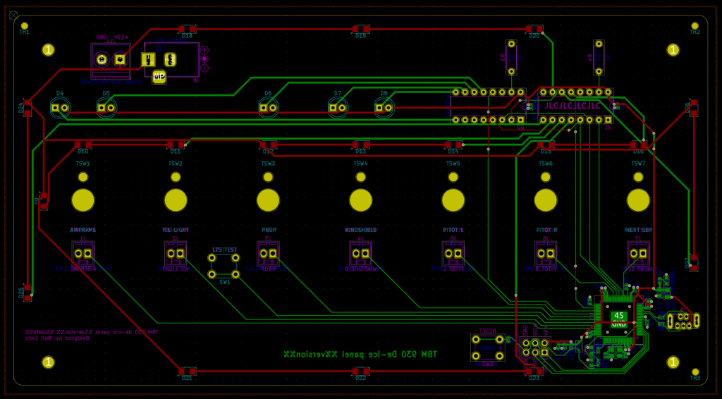
The final PCB design sent to fabrication.
Routing the power traces
For cost reasons I really wanted to keep this to a 2-layer board which meant I couldn’t fall back to a dedicated power plane on an inner board layer. I’ve done PCBs in the past and routing the power traces was pretty easy but dealing with the ATmega32u4 was… tricky.
Package selection makes a difference here. Originally I tried to use a QFN package but those pins are tiny and I was really having a tough go of it. Things got a lot easier when I switched to TQFP, which conveniently is easier to hand solder as well.
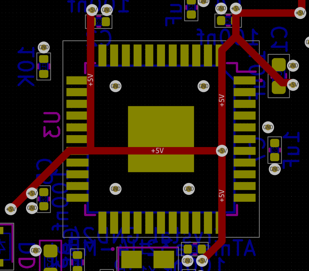
The other trick is to remember you can run traces underneath the chip (something I always forget). To get all the VCC pins connected I took full advantage of this, running all the power traces on the front side of the board and using vias to pop them out on the back side where the 32u4 lived:
Power traces connecting the VCC pins on an ATmega32u4
Placing the decoupling capacitors and oscillator
The capacitors and oscillator should be placed as close to the ATmega32u4 as possible. I tried several layouts and what worked for me was to use teeny tiny capacitors (0402) placed close to the power and ground pins, but still leaving enough space to get a soldering iron in since I was going to hand solder the 32u4. Since I planned to use JLCPCB’s SMT assembly service for all the small components on the back of the board I thankfully didn’t have to worry about trying to solder the tiny capacitors.
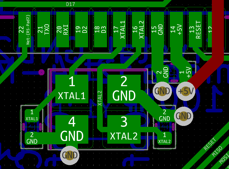
The oscillator and its associated capacitors also took a bit of layout tweaking but eventually I settled on this:
The crystal oscillator and its associated capacitors.
The other thing that helped me with this part of the layout was to route all the power traces first.
Routing the data lines
The data lines coming off the GPIO pins were something I redid multiple times. My initial pin assignment in the schematic for each of the data lines was essentially arbitrary and many of them just didn’t make sense when it came to doing the board layout. I kept hitting situations where I was jumping traces between board layers and the overall trace layout was messy.
This is where going back to the schematic and making changes is valuable. There are only two lines that have to be on pins with PWM support (the two that control LED brightness). All the other data lines can go on any GOIP pin.
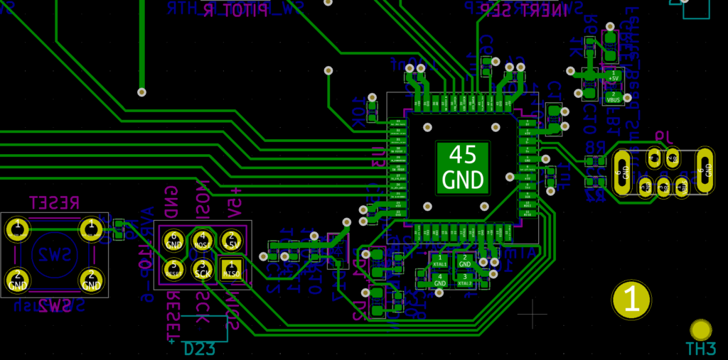
I did several revisions where I swapped data lines to different pins, doing my best to select pins that were closer to where the traces eventually had to run. Don’t be afraid to revise your schematic! In the end I came up with this:
Data lines coming out of the ATmega32u4.
The traces are clean, flow reasonably directly to where they need to go, and only a handful of vias were required to jump over other traces.