It’s got better and easier to understand documentation
It’s easier to get firmware installed when your board arrives
It’s impossible to brick, you can always put it in bootloader mode
The only little gotcha is the RP2040 runs at 3V3 instead of 5V, which means you may need to use a level shifter with certain ICs (most notably the MAX7219) for safe operation.
Feb 26, 2023: While this information is still accurate I would never, ever, do an ATmega32u4 PCB anymore. Instead I use an RP2040 chip. So much easier to find, cheaper, and easier to deal with.
It’s one thing to design a nice schematic for a board based on an ATmega32u4. It’s quite another to figure out how to get all the traces to work well on the actual PCB you’re planning to send off to fabrication.
In this post, part 2 in a series, I’ll walk through some of the things that worked for me when trying to solve layout issues during my custom PCB design.
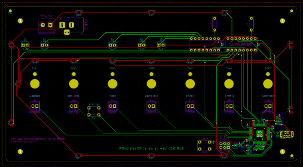
The final PCB design sent to fabrication.
Routing the power traces
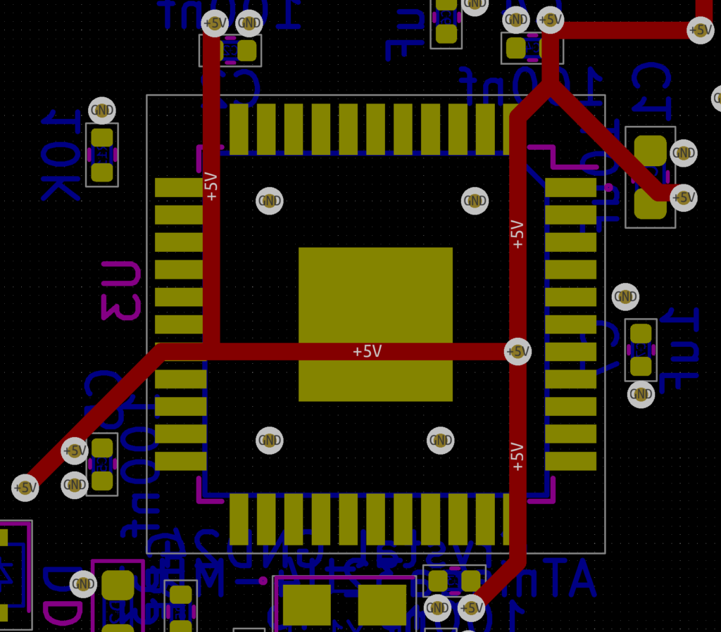
For cost reasons I really wanted to keep this to a 2-layer board which meant I couldn’t fall back to a dedicated power plane on an inner board layer. I’ve done PCBs in the past and routing the power traces was pretty easy but dealing with the ATmega32u4 was… tricky.
Package selection makes a difference here. Originally I tried to use a QFN package but those pins are tiny and I was really having a tough go of it. Things got a lot easier when I switched to TQFP, which conveniently is easier to hand solder as well.
The other trick is to remember you can run traces underneath the chip (something I always forget). To get all the VCC pins connected I took full advantage of this, running all the power traces on the front side of the board and using vias to pop them out on the back side where the 32u4 lived:
Power traces connecting the VCC pins on an ATmega32u4
Placing the decoupling capacitors and oscillator
The capacitors and oscillator should be placed as close to the ATmega32u4 as possible. I tried several layouts and what worked for me was to use teeny tiny capacitors (0402) placed close to the power and ground pins, but still leaving enough space to get a soldering iron in since I was going to hand solder the 32u4. Since I planned to use JLCPCB’s SMT assembly service for all the small components on the back of the board I thankfully didn’t have to worry about trying to solder the tiny capacitors.
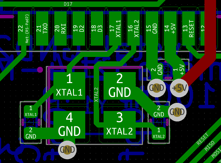
The oscillator and its associated capacitors also took a bit of layout tweaking but eventually I settled on this:
The crystal oscillator and its associated capacitors.
The other thing that helped me with this part of the layout was to route all the power traces first.
Routing the data lines
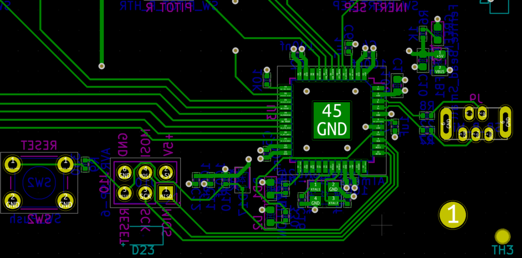
The data lines coming off the GPIO pins were something I redid multiple times. My initial pin assignment in the schematic for each of the data lines was essentially arbitrary and many of them just didn’t make sense when it came to doing the board layout. I kept hitting situations where I was jumping traces between board layers and the overall trace layout was messy.
This is where going back to the schematic and making changes is valuable. There are only two lines that have to be on pins with PWM support (the two that control LED brightness). All the other data lines can go on any GOIP pin.
I did several revisions where I swapped data lines to different pins, doing my best to select pins that were closer to where the traces eventually had to run. Don’t be afraid to revise your schematic! In the end I came up with this:
Data lines coming out of the ATmega32u4.
The traces are clean, flow reasonably directly to where they need to go, and only a handful of vias were required to jump over other traces.
Feb 26, 2023: While this information is still accurate I would never, ever, do an ATmega32u4 PCB anymore. Instead I use an RP2040 chip. So much easier to find, cheaper, and easier to deal with.
I built a custom PCB that replicates the TBM930 de-ice panel for use with Microsoft Flight Simulator 2020 and Mobiflight. This is part 1 of a series where I walk through how I managed to do it with an ATmega32u4 directly on the PCB instead of relying on an external Arduino board.
Why an ATmega32u4 (the chip used on the SparkFun Pro Micro) instead of the ATmega2560 (the chip used on the Arduino Mega 2560)? Easy: onboard USB. The 2560 doesn’t have onboard USB and if you look at the schematic for the Mega 2560 you’ll see it also has… a 32u4 to handle the USB communication.
The chip itself has, as you’d expect, a full datasheet. But if you’re like me you just want to know what decoupling capacitors and whatnot are required and how to lay them out on a PCB. Sadly that isn’t really explained in the datasheet so I wound up doing a lot of reading in random forums of people trying to do similar custom boards and looking at the schematics for the Pro Micro and Arduino Leonardo. Distilling all that down got me this schematic:
Schematic illustrating an ATmega32u4’s basic connections.
Important things to note:
Every VCC and AVCC pin gets a 100nf/0.1uF capacitor
UCAP gets a 1uF capacitor
AREF gets a 1uF capacitor
VBUS and UVCC share a 10uF capacitor
Pin 33 (~HWB/PE2) gets tied to ground through a 10kΩ resistor since the Arduino bootloader doesn’t use the HWB feature
In addition the incoming USB port has components to ensure proper power and USB operation. I wanted to include ESD protection but JLCPB didn’t have any available as basic parts so I left it out.
Necessary components for the USB input to an ATmega32u4.
Of note are the 22Ω resistors on the D+ and D- lines.
The Arduino bootloader expects the 32u4 to have an external oscillator providing the clock so that also needs to be included in the schematic:
Necessary components for an external crystal oscillator with an ATmega32u4.
The oscillator is 16MHz and per the datasheet I added 20pF capacitors. 22pF capacitors should work too but 20pF is what I had on hand so that’s what I used.
Finally there has to be a way to get the bootloader onto the chip. I did that by exposing an AVR-ISP header and reset switch on the board. The reset switch really wasn’t necessary but it was easy to include so I added it. The reset circuit design is pulled directly from the chip’s application notes (see figure 2-1).
AVR-ISP and reset circuit for an ATmega32u4.
That’s all it takes! When I first looked at the schematics for the Sparkfun Pro Micro I found it pretty intimidating (and frankly quite messy) but once I walked through it the actual required components aren’t that bad.
The complete schematic is available in GitHub. To see how this got laid out on the PCB check out part 2 of the series.
Mobiflight is an amazing piece of software that makes it possible to easily make physical controls for planes in flight simulators with an off-the-shelf Arduino, some buttons, and some LEDs. I’ve had a ton of fun with it and even designed a custom PCB for a general purpose radio stack. The radio stack is cool but it still relines on an Arduino being stuck to the back.
But did you know it’s possible to make a custom PCB with an ATmega32u4 right on the board and have it work with Mobiflight, no external Arduino required?
TBM930 de-ice panel custom PCB for use with Microsoft Flight Simulator 2020 and Mobiflight.
In this series of blog posts I’ll walk through how I designed the TBM930 de-ice panel as a custom PCB with an onboard ATmega32u4 that works with Mobiflight.
While this PCB is intended for use with Mobiflight the steps involved apply to any PCB you might want to make that uses the 32u4.