Uncovering input events using the MSFS2024 model behavior dialog
This post is out-of-date. For current instructions see the MobiFlight documentation.
This post is out-of-date. For current instructions see the MobiFlight documentation.
Feb 26, 2023: While this information is still accurate I would never, ever, do an ATmega32u4 PCB anymore. Instead I use an RP2040 chip. So much easier to find, cheaper, and easier to deal with.
It’s one thing to design a nice schematic for a board based on an ATmega32u4. It’s quite another to figure out how to get all the traces to work well on the actual PCB you’re planning to send off to fabrication.
In this post, part 2 in a series, I’ll walk through some of the things that worked for me when trying to solve layout issues during my custom PCB design.
For cost reasons I really wanted to keep this to a 2-layer board which meant I couldn’t fall back to a dedicated power plane on an inner board layer. I’ve done PCBs in the past and routing the power traces was pretty easy but dealing with the ATmega32u4 was… tricky.
Package selection makes a difference here. Originally I tried to use a QFN package but those pins are tiny and I was really having a tough go of it. Things got a lot easier when I switched to TQFP, which conveniently is easier to hand solder as well.
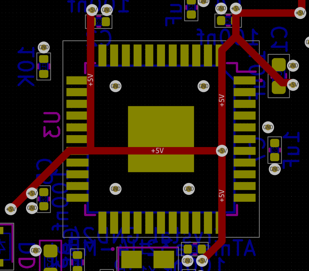
The other trick is to remember you can run traces underneath the chip (something I always forget). To get all the VCC pins connected I took full advantage of this, running all the power traces on the front side of the board and using vias to pop them out on the back side where the 32u4 lived:
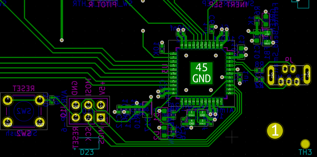
The capacitors and oscillator should be placed as close to the ATmega32u4 as possible. I tried several layouts and what worked for me was to use teeny tiny capacitors (0402) placed close to the power and ground pins, but still leaving enough space to get a soldering iron in since I was going to hand solder the 32u4. Since I planned to use JLCPCB’s SMT assembly service for all the small components on the back of the board I thankfully didn’t have to worry about trying to solder the tiny capacitors.
The oscillator and its associated capacitors also took a bit of layout tweaking but eventually I settled on this:
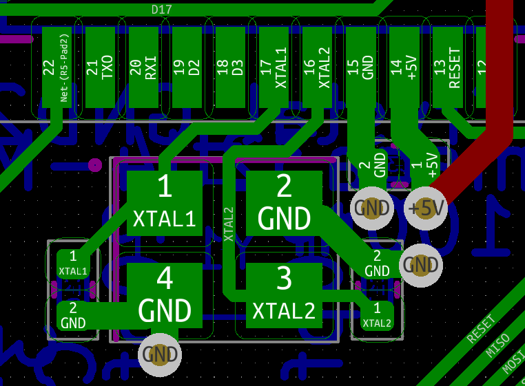
The other thing that helped me with this part of the layout was to route all the power traces first.
The data lines coming off the GPIO pins were something I redid multiple times. My initial pin assignment in the schematic for each of the data lines was essentially arbitrary and many of them just didn’t make sense when it came to doing the board layout. I kept hitting situations where I was jumping traces between board layers and the overall trace layout was messy.
This is where going back to the schematic and making changes is valuable. There are only two lines that have to be on pins with PWM support (the two that control LED brightness). All the other data lines can go on any GOIP pin.
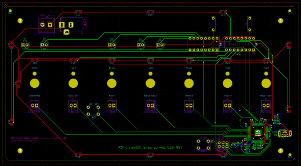
I did several revisions where I swapped data lines to different pins, doing my best to select pins that were closer to where the traces eventually had to run. Don’t be afraid to revise your schematic! In the end I came up with this:
The traces are clean, flow reasonably directly to where they need to go, and only a handful of vias were required to jump over other traces.
In a previous post I walked through how to apply workarounds to MSFS2020 to get access to Bvars from MobiFlight.
If you run into trouble getting the workaround to take effect here are some ways to debug it using developer tools in MSFS2020. All of these techniques assume you have developer mode enabled in flight simulator and have the Model Behaviour dialog open.
Open the Model Behaviour dialog and switch to the Local Variables tab. Use the search box to filter the list to the custom Lvar name created for your workaround. In the screenshot below the list is filtered to the Lvar wrapping the Bvar for the TBM930 inertial separator:

With the variable visible trigger the input event using your attached device (e.g. flip the physical switch to the on position). You should see the Lvar change, first to the value specified in MobiFlight (e.g. two) then to one less than that value, then zero. For example, when turning the inertial separator on the values should be 2, 1, then 0.
If you do not see the Lvar value changing the issue could be:
If the Lvar is changing but the plane isn’t reflecting the new state the next step is to verify the Bvar is changing.
Open the Model Behaviour dialog and switch to the Input Events tab. Find the Bvar that’s being wrapped by the workaround and click the <Start tracking> button. This will add the Bvar to the list on the right side of the dialog and show its current value.

With the dialog open trigger the custom event using MobiFlight, e.g. by flipping your switch on. The Bvar should update to the set value. For example, in the case of the TBM930 inertial separator the value should become 1.
If the Bvar doesn’t change then verify the workaround RPN is setting the correct Bvar.
An updated version of this page is available in the official MobiFlight documentation.
One of the most common questions asked in the MobiFlight Discord is how to control something in a plane. With the incredible MSFS2020 SimConnect event support in MobiFlight pretty much anything is possible… if you can figure out what event to use.
HubHop is a great resource and should be everyone’s first stop when researching events. Chances are someone else has already done the digging and figured out what works.
But what do you do if the thing you want isn’t in HubHop? That’s where the model behaviour dialog comes in. Let’s walk through how to use it to research the event to use for setting parking brake on a TBM930.
This step is easy 😀 Run Flight Simulator then go to Options > General Options > Developers and toggle Developer Mode to On. Restart flight simulator (restarting is important otherwise the later steps won’t show anything useful).
This is also easy 😀 Use the World map to spawn the plane you want to dig into somewhere in the world. For this example I spawned the TBM930 at KPAE.
Once you’ve spawned at the airport open the model behavior dialog from the developer menu across the top of the screen by going to Tools > Behaviors. Then do the following:
Steps 3 and 4 ensure that the code behind the different events will be visible for us to inspect.
When you’re done the dialog should look like this:

Not seeing any events listed? Check and make sure that you’ve selected the correct XML file from the dropdown. If it doesn’t say INTERIOR in the name you probably have the wrong one selected.
Still don’t see any events listed? Sometimes it happens. Try restarting the sim and going through steps 1-5 again.
This is where things get a bit tricky since there’s no search feature on the InputEvents tab. It helps to have some idea of what system the input you want belongs to. In the case of the parking brake I guessed that since it relates to wheels it would be in the LANDING_GEAR section so I expanded that:

Sometimes it’s nice to be lucky 😀 LANDING_GEAR_ParkingBrake looks promising. To find out what makes that specific event work:
Those steps result in a dialog like this:

At this point we know exactly how the sim manages the parking brake:
p0 0 max 1 min (>K:PARKING_BRAKE_SET)
(A:BRAKE PARKING POSITION, bool) 100 * (>L:ParkingBrake_Position)
But what does it mean? How do we use it? This is where it takes a bit of practice and understanding RPN. Generally speaking you are trying to identify which Kvar is getting used. In this case it looks like (K:PARKING_BRAKE_SET) is the magic, and it is either 0 or 1. Chances are 0 means off and 1 means on.
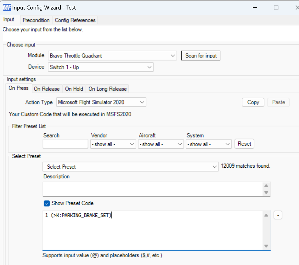
At this point you can jump over to MobiFlight and try the event out. Create a new input config with an action type of Microsoft Flight Simulator 2020 and check the Show Preset Code box to get a text box for the event code. For this example, in On Press, I would try this:
1 (>K:PARKING_BRAKE_SET)
And for On Release I would try this:
0 (>K:PARKING_BRAKE_SET)
It should look something like this:
Once you’ve confirmed the event works as expected head on over to HubHop and add entries so everyone else can benefit going forward!
Realistically this is all a big pain and shouldn’t be this hard. Upvote the feature request to let Asobo know you’d like a proper event system where it isn’t necessary to dig through RPN code to make the plane work with external controls!
Update 2024-02-10: If you are trying to access the inaccessible switches on the TBM930 there’s an add-on available that exposes them as Lvars. You can use that add-on to implement the below workaround without having to edit the file yourself.
With the release of Sim Update 5, Asobo and Microsoft dramatically changed how sim events work to manipulate airplane controls. Unfortunately this broke the experience for many switches when trying to set them via MobiFlight.
Wish you didn’t have to apply this workaround? Me too. Help change this by upvoting the feature request for better access!
What happens without a workaround is you can control the switches via MobiFlight but the in-sim switch doesn’t update to reflect the current state. For example you can turn the inertial separator of the TBM930 on with MobiFlight and the MFD will show the “Inert sep” warning correctly but the switch on the in-sim de-ice panel will still be in the off position.
Luckily there’s a workaround. In this post I’ll walk through the steps to apply the workaround for two switches in the TBM 930: propeller de-ice and inertial separator.
Technically you can make this change to the sim files directly but since the TBM930 improvement mod is a must-have if you fly the TBM930 we’ll be applying the workaround to its files instead.
The file to edit is located in the aircraft-tbm930-improvement\SimObjects\Airplanes\Asobo_TBM930\model folder, inside the MSFS2020 Community folder. Open the tbm930_interior.xml in the text editor of your choice. I prefer Visual Studio Code but it can be any text editor like Notepad, Notepad++, etc.
Locate the following section near the top of the tbm930_interior.xml file:
    <!-- INSTRUMENT ################################# -->
    <Component ID="INSTRUMENT">
Above that section paste the workaround in:
<!-- ############################################### -->
<Component ID="MobiFlight_External_Control">
<UseTemplate Name="ASOBO_GT_Update">
<UPDATE_CODE>
(L:MF_TBM930_DEICE_Engine_1_Set, Number) s0 0 > if{ l0 1 - (>B:DEICE_Engine_1_Set) 0 (>L:MF_TBM930_DEICE_Engine_1_Set) }
</UPDATE_CODE>
<FREQUENCY>1</FREQUENCY>
</UseTemplate>
</Component>
The resulting file should look like this:

Save the file, close it, and restart Microsoft Flight Simulator.
For the On Press and On Release actions of each switch you’ll need to update the configuration to use the MSFS2020 – Custom Input option and add the correct custom event. They are:
| Switch | Event | Custom input |
| Prop de-ice | On Press | 2 (>L:MF_TBM930_DEICE_Propeller_1_Set) |
| Prop de-ice | On Release | 1 (>L:MF_TBM930_DEICE_Propeller_1_Set) |
| Inertial separator | On Press | 2 (L:>MF_TBM930_DEICE_Engine_1_Set) |
| Inertial separator | On Release | 1 (L:>MF_TBM930_DEICE_Engine_1_Set) |
For example the On Press event for the prop de-ice switch should look like this:
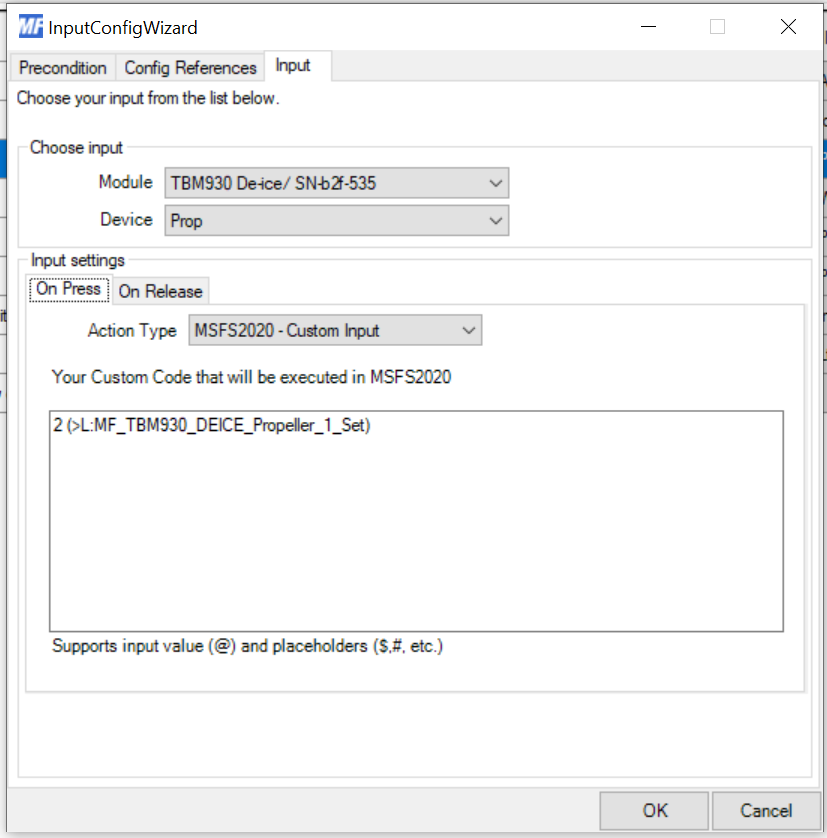
That’s all there is to it! Now you’re ready to fly and enjoy the physical switches working as they should with the sim.
While this post focused on modifying the TBM930 the same technique works on other planes as well. For other planes you’ll edit the *_interior.xml file for that plane, likely in the Asobo official file, and insert a similar block of XML that defines new events to wrap the Bvars in the sim.
When creating your custom event it’s important to offset the value by one from 0. This ensures the event only takes effect if the value is explicitly set by MobiFlight. For example if the sim expects a value of 0 to turn something off and 1 to turn something on the custom event should instead take a value of 1 for off, 2 for on, and then subtract 1 from the provided value before passing it to the sim.
You can see this in action with any of the above custom events, for example:
(L:MF_TBM930_FUEL_Selection_Set, Number) s0 0 > if{ l0 1 - (>B:FUEL_Selection_set) 0 (>L:MF_TBM930_FUEL_Selection_Set) }
The custom event checks to see if the value is greater than 0 before doing anything. If it’s 0 nothing happens and the sim will function as if the workaround isn’t applied at all. If it’s greater than 0 then 1 is subtracted from the specified value (to turn it into what the sim expects), then it is passed to the sim.
The workaround will get overwritten every time a new version of the TBM930 improvement mod is released. You’ll need to go back to step 3 and apply the change after every improvement mod update.
There are other switches in the TBM930 that need these changes, such as the fuel selector switch. You can find them documented on HubHop, the unofficial repository of all MSFS2020 events. When adding additional workarounds you only need to insert the new Lvar from hubhop into the existing workaround block applied in step 3. For example to apply the workaround for the fuel selector switch the workaround block winds up looking like this:

The MobiFlight wiki is a wealth of knowledge for how to do things like this. Check out the article on how to use custom input page or how to use the developer tools to uncover events.
2021-10-14: Updated RPN to use registers instead of duplicating on the stack. Corrected a > to >.
Feb 26, 2023: While this information is still accurate I would never, ever, do an ATmega32u4 PCB anymore. Instead I use an RP2040 chip. So much easier to find, cheaper, and easier to deal with.
I built a custom PCB that replicates the TBM930 de-ice panel for use with Microsoft Flight Simulator 2020 and Mobiflight. This is part 1 of a series where I walk through how I managed to do it with an ATmega32u4 directly on the PCB instead of relying on an external Arduino board.
Why an ATmega32u4 (the chip used on the SparkFun Pro Micro) instead of the ATmega2560 (the chip used on the Arduino Mega 2560)? Easy: onboard USB. The 2560 doesn’t have onboard USB and if you look at the schematic for the Mega 2560 you’ll see it also has… a 32u4 to handle the USB communication.
The chip itself has, as you’d expect, a full datasheet. But if you’re like me you just want to know what decoupling capacitors and whatnot are required and how to lay them out on a PCB. Sadly that isn’t really explained in the datasheet so I wound up doing a lot of reading in random forums of people trying to do similar custom boards and looking at the schematics for the Pro Micro and Arduino Leonardo. Distilling all that down got me this schematic:

Important things to note:
In addition the incoming USB port has components to ensure proper power and USB operation. I wanted to include ESD protection but JLCPB didn’t have any available as basic parts so I left it out.

Of note are the 22Ω resistors on the D+ and D- lines.
The Arduino bootloader expects the 32u4 to have an external oscillator providing the clock so that also needs to be included in the schematic:

The oscillator is 16MHz and per the datasheet I added 20pF capacitors. 22pF capacitors should work too but 20pF is what I had on hand so that’s what I used.
Finally there has to be a way to get the bootloader onto the chip. I did that by exposing an AVR-ISP header and reset switch on the board. The reset switch really wasn’t necessary but it was easy to include so I added it. The reset circuit design is pulled directly from the chip’s application notes (see figure 2-1).

That’s all it takes! When I first looked at the schematics for the Sparkfun Pro Micro I found it pretty intimidating (and frankly quite messy) but once I walked through it the actual required components aren’t that bad.
The complete schematic is available in GitHub. To see how this got laid out on the PCB check out part 2 of the series.
Mobiflight is an amazing piece of software that makes it possible to easily make physical controls for planes in flight simulators with an off-the-shelf Arduino, some buttons, and some LEDs. I’ve had a ton of fun with it and even designed a custom PCB for a general purpose radio stack. The radio stack is cool but it still relines on an Arduino being stuck to the back.
But did you know it’s possible to make a custom PCB with an ATmega32u4 right on the board and have it work with Mobiflight, no external Arduino required?

In this series of blog posts I’ll walk through how I designed the TBM930 de-ice panel as a custom PCB with an onboard ATmega32u4 that works with Mobiflight.
While this PCB is intended for use with Mobiflight the steps involved apply to any PCB you might want to make that uses the 32u4.
Questions about any of the above after reading through it? Come ask in the MobiFlight Discord!
Powered by sciolism 2019 and WordPress.